The brains of Optic Flow begin with an Arduino Uno and the custom-built circuit.
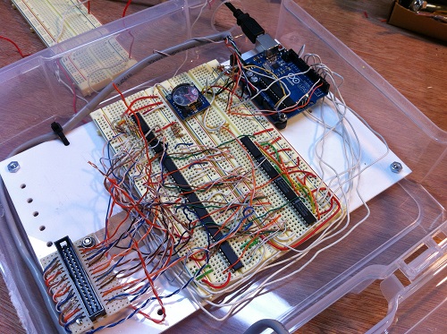
The Arduino can only switch its microprocessor pins on or off, at a low 5 volts. That’s not enough to control all the components of Optic Flow, like the ten motors. The artist designed and built a custom electronic circuit that takes the low-voltage signals from the Arduino and does something useful with them.
-
An internal network called an “I2C serial bus” to communicate to the light pendants, real time clock and LCD display.
-
Rotary encoder to allow the user to select “mood” programs to run.
- Isolated electrical circuit that provides a high-power electrical current for the ten motors, and which won’t damage the other components. This isolated circuit uses “H-Bridge” chips. These are dedicated chips that can turn on-or-off each motor individually, and reverse the direction of the motor.
- A bank of daisy-chained “shift registers.” These are chips that expand the number of other components or devices that the Arduino can control